
The World's Longest Swing Bridge — and Why the Real Work Was Underground
El-Ferdan Railway Bridge holds the record as the world's longest swing railway bridge — two counter-rotating spans totalling 340 metres, crossing the Suez Canal at km 68.175 to connect Egypt's national rail network with Sinai. My role on this project (2019–2020) as Executive Director and Owner Representative covered the full railway completion works: corridor earthworks, underground utility crossings, and VDC 5D production — all across a site divided by water.
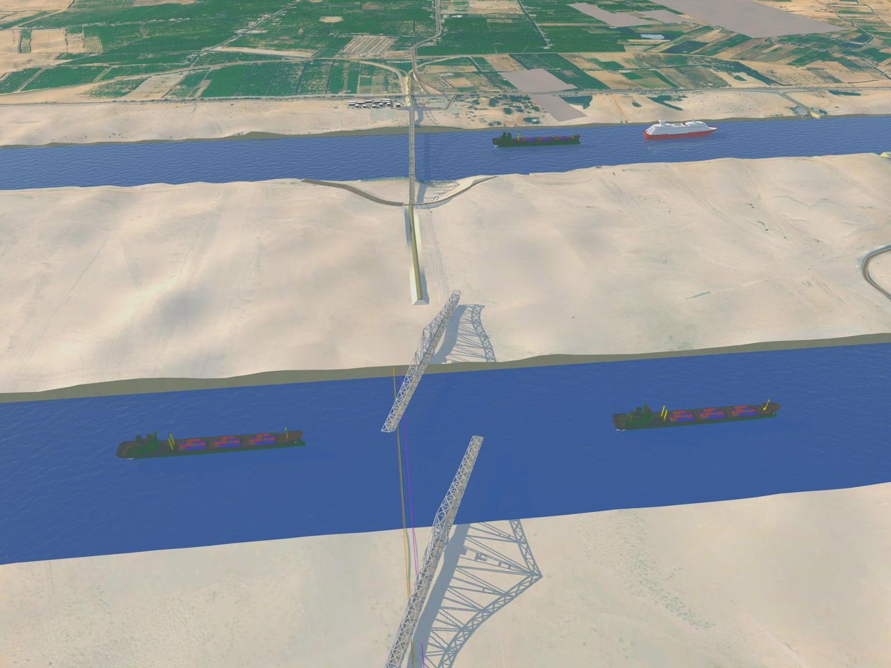
The Geography That Defines Every Decision
The site layout is unique. The 2015 New Suez Canal expansion created a parallel channel alongside the original, with a middle island between them. The railway alignment must cross both waterways:
West Bank → Old Suez Canal → Middle Island → New Canal (2015) → East Bank (Sinai)
Every equipment delivery, material shipment, and crew movement had to cross water at least once — sometimes twice. This is not a logistical inconvenience; it is a fundamental engineering constraint that shapes the entire programme.
Railway Corridor Earthworks — The 300,000 m³ Discovery
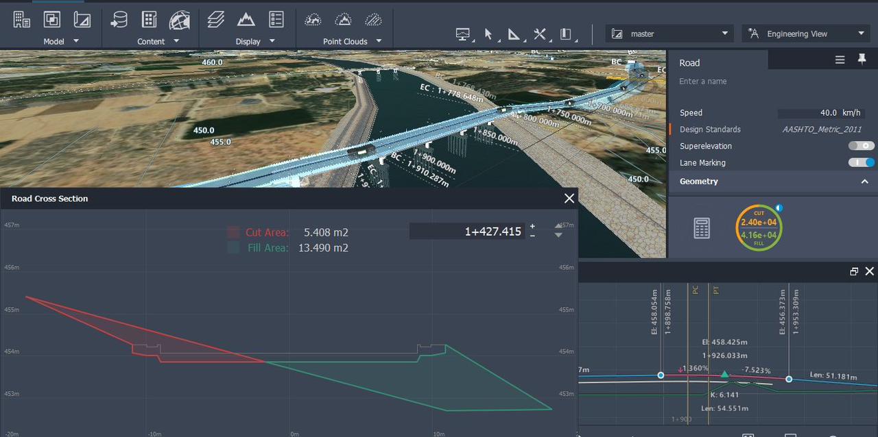
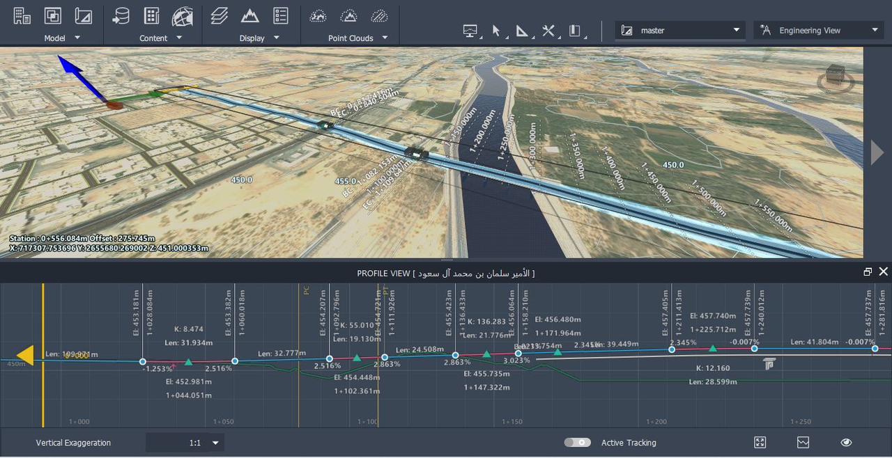
The railway completion required full earthwork preparation of the corridor: clearing the right-of-way, establishing the longitudinal profile (vertical alignment), and executing cut/fill operations to bring the track bed to design level.
Using Civil 3D and InfraWorks, I built the full corridor model:
- Imported survey points to generate the existing ground surface
- Defined the corridor with full subassembly parameters (slopes, benching, drainage)
- Generated cross-sections at 20m intervals along the full alignment
- Ran mass haul analysis to optimise cut-to-fill distribution and identify borrow requirements
Total calculated volume: ~1,000,000 m³ of cut, fill, and backfill.
The contractor's submitted quantity report claimed ~1,300,000 m³.
A difference of 300,000 cubic metres — equivalent to filling over 120 Olympic swimming pools — was identified and challenged with full model-backed documentation. The owner paid on the verified figure.
This is precisely what BIM-based quantity verification exists for. The Civil 3D model is not a visualisation tool — it is a financial control instrument.
Sonar Survey — Seeing Through the Water
Before any underground work could be designed, we needed accurate cross-sectional profiles of both canal beds — data that no standard survey can provide above water.
We commissioned a bathymetric sonar survey conducted from survey vessels traversing the canal above the proposed crossing alignments. The sonar produced:
- Accurate cross-sections of both canal beds at the crossing locations
- Depth maps identifying the deepest point in each channel
- Seabed texture and sediment data informing soil classification
- Detection of any submerged obstructions along the HDD corridor
These cross-sections were the foundation of the HDD bore path design — defining entry angles, minimum cover depth, and exit coordinates on the opposite bank.
Horizontal Directional Drilling — Crossing the Canal Without Touching It
The utility networks serving the bridge and railway (power cables, fibre optic, railway signalling cables) had to cross under both canal channels. Open-cut trenching across an active international shipping lane is not an option. The method: Horizontal Directional Drilling (HDD).
HDD executes a controlled underground bore from surface on one bank, curving down under the canal bed, and emerging on the opposite bank — entirely below the waterway, with zero impact on navigation.
The three-phase process:
- Pilot Bore: A small-diameter drill rod (~100mm) follows a pre-programmed path guided by a downhole steering tool transmitting real-time position data. The bore passes under the canal at a depth providing the required minimum cover over the canal bed (typically 5–8m minimum for navigable waterways).
- Reaming: The pilot hole is progressively enlarged in multiple passes until it reaches the diameter required to accommodate the utility casing.
- Pipe Pull-Back: The pre-fabricated casing or conduit bundle is attached to the drill string and pulled through the completed bore in a single continuous operation.
Two HDD operations were required: one under the Old Canal, one under the New Canal — each designed independently based on its own sonar cross-section data.
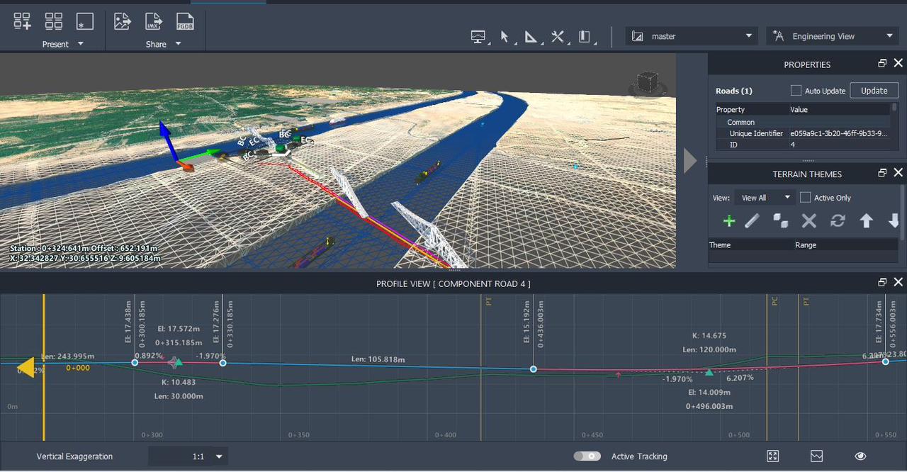
VDC 5D — The Bridge Before It Was Built
For a project of this complexity — three work zones, two water crossings, underground utilities, and a record-scale swing mechanism — conventional 2D drawings and schedules are insufficient as coordination and reporting tools. The VDC 5D model delivered something different.
What the VDC output contains:
- 4D Construction Sequence: Every phase of works — earthworks, pile installation, abutments, pier construction, swing span erection, track laying, utility installation — animated in time sequence at FHD resolution. The complete bridge "grows" from the ground in real time.
- 5D Quantity & Cost Integration: Each phase carries live quantity and cost data: cumulative volumes, earned value, S-curve comparison (Planned vs. Actual), CPI and SPI indicators updating with each time step.
- Clash Detection Results: Colour-coded interference flags embedded in the model showing resolved and outstanding clashes between structural, civil, and utility elements.
- Cross-Section Views: Interactive cut-through views at any chainage showing the underground utility positions relative to canal bed and structure foundations.
This level of output transforms the VDC model from a presentation asset into a live project management instrument — used in owner progress meetings, contractor payment certifications, and dispute resolution documentation.
A VDC 5D model at this level does not just show what was built. It shows what was spent, what was planned, what deviated, and why — frame by frame.
What This Project Represents
El-Ferdan combined four disciplines that rarely meet on a single project: precision earthwork quantity verification, subsea geotechnical investigation, trenchless utility installation, and high-fidelity VDC production — all on a site that required marine logistics to access. Every element demanded independent technical expertise. Managing all four simultaneously, on behalf of the owner, while maintaining schedule and protecting the client's financial position, is what executive-level site representation means in practice.