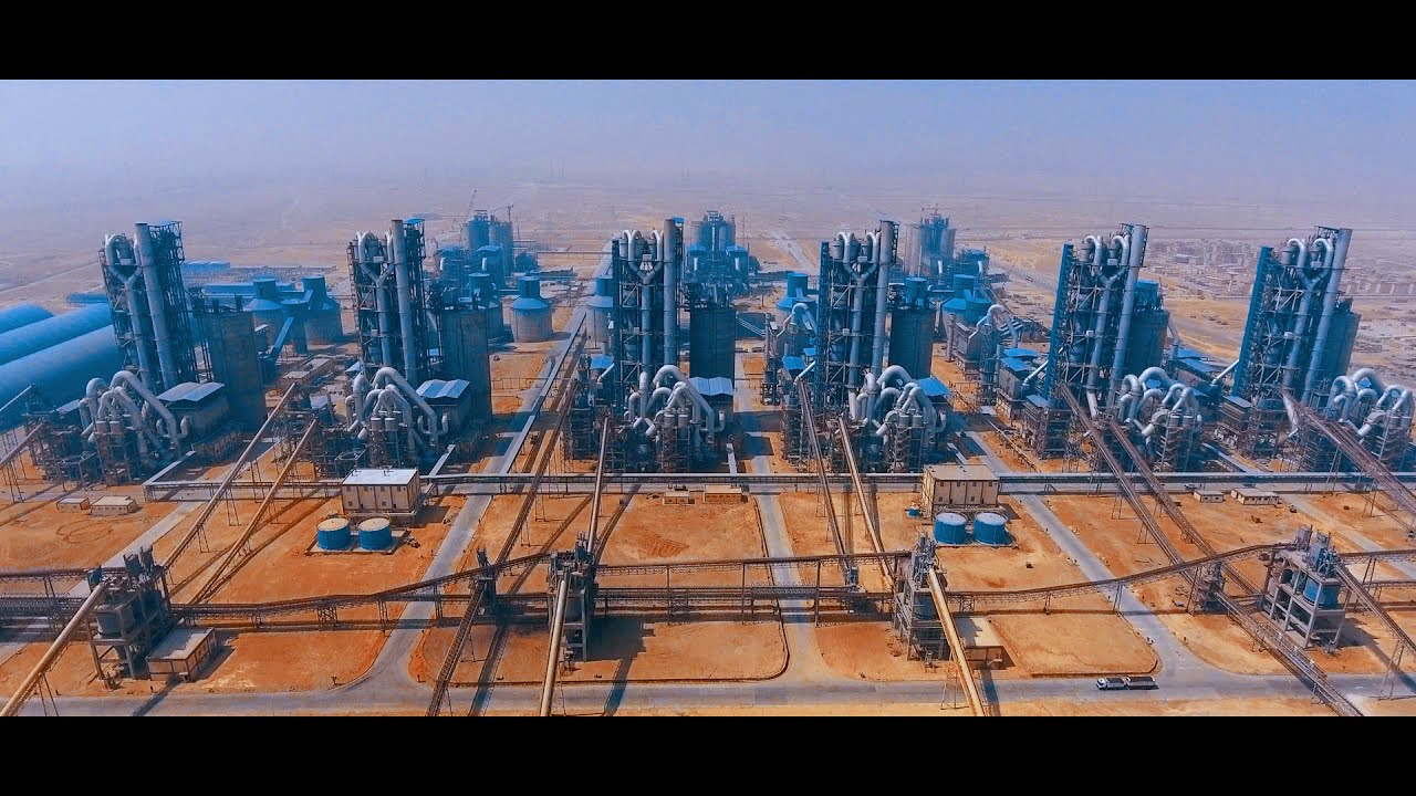
The Scale: Six Factories Built as One
In 2015, I joined one of the largest industrial construction projects in Africa — Beni Suef Cement Plant. Not a single production line, but six complete cement lines running in parallel, each producing 6,000 tonnes of clinker per day, for a total capacity of 36,000 TPD, across a site of 5 km², with a total contract value exceeding $1.12 Billion. My role was as Owner Representative for the Engineering Authority of Armed Forces — the technical eye responsible for every cubic metre of concrete poured, every road built, and every structure that rose.
How Cement Is Made — The Full Production Chain
To understand the construction challenges, you need to understand the process we were building for. The cement production cycle follows a precise sequence of physical and chemical transformations:
- Limestone Quarry & Crusher: Raw limestone is extracted and crushed in primary and secondary crushers down to ~25mm fragments.
- Raw Material Storage: Limestone, clay, sand, and iron ore are stored in large pre-homogenisation yards to ensure chemical consistency.
- Raw Mill: All raw materials are ground together into a fine powder (~90 microns) called raw meal, then stored in raw meal silos.
- Pre-Heater Tower (100m+): The tallest structure on site. Raw meal enters from the top while hot gases rise from below, progressively heating the material before it enters the kiln — a critical energy-saving stage.
- Rotary Kiln: A massive rotating steel cylinder (~5.5m diameter, 70m+ long) burning materials at 1,450°C. This is where clinker is formed.
- Clinker Cooler: Clinker exits the kiln at ~1,400°C and is rapidly cooled to handling temperature. The cooling rate directly determines clinker quality.
- Cement Mill: Clinker is ground with gypsum (and sometimes limestone or additives) to produce the final cement product.
- Cement Silos: Cylindrical storage structures holding 10,000–20,000 tonnes each, from which cement is dispatched in bulk or bagged.
I supervised the civil and structural construction of two full production lines across this complete chain — from raw material intake structures to the final cement silos.
Challenge 1 — Six Ready-Mix Stations, One Standard
Feeding concrete to a 5 km² site requires a distributed batching infrastructure. We commissioned 6 Ready-Mix concrete batching plants positioned strategically to minimise transport time and maintain workability.
The real challenge was not having the plants — it was achieving uniform output across all six. Each plant was individually calibrated (aggregate scales, cement weighers, water meters), and every concrete grade used on site had a dedicated Mix Design and validated Trial Mix program before any structural pour was approved. Quality control testing — Slump, Cube specimens, Compressive Strength, and Water-Cement ratio — was executed systematically on every pour.
Challenge 2 — Self-Compacting Concrete and the Glenium Advantage
In several structural zones — particularly at equipment foundations and heavily reinforced walls — conventional vibrated concrete was simply not practical. Rebar density was too high for a vibrator to penetrate effectively, making honeycombing and segregation near-inevitable.
The solution was Self-Compacting Concrete (SCC) formulated with Glenium, a third-generation polycarboxylate-based superplasticizer (PCE) by BASF. Glenium delivers exceptional flowability (Flow >650mm on the flow table test) while maintaining:
- Full segregation resistance — no bleed water or aggregate settling
- Ability to pass through congested reinforcement without any mechanical assistance
- A mirror-quality formed surface with zero honeycombing
SCC with Glenium was not just a material choice — it was the only engineering solution that could guarantee structural integrity in those zones.
Challenge 3 — Mass Concrete and the War Against Heat
The thick foundation mats for preheater towers, kilns, and silos required large-volume continuous pours — what is classified as Mass Concrete. The problem: cement hydration is an exothermic reaction. In large pours, heat accumulates in the core while the surface cools — generating tensile stresses that exceed the early-age tensile strength of concrete, producing deep thermal cracks.
The solution was an embedded Pipe Cooling System — a network of galvanised steel pipes cast inside the concrete through which chilled water circulates continuously during and after pouring, exactly like an engine cooling system but inside the structure.
My daily responsibilities on mass concrete pours included:
- Reading inlet and outlet water temperatures from every cooling circuit daily
- Ensuring the temperature differential never exceeded 25°C (per ACI 207 standard)
- Adjusting flow rates based on readings to maintain safe gradients
- Logging all thermal data and correlating with daily QC reports submitted to the client
Failure here would have meant structural cracks in foundation pads carrying thousands of tonnes. We logged zero thermal cracking incidents across all mass concrete pours on the project.
Challenge 4 — Slip Form: Engineering at the Speed of Setting Time
Slip Form (Sliding Formwork) is the construction method used for tall vertical structures — preheater towers, silos, and shafts reaching over 100 metres. A steel formwork panel moves continuously upward at a controlled rate while fresh concrete is placed below, gaining strength as the form rises above it.
The margin for error is almost zero. Two critical failure modes exist:
- Free Lift: If the form moves before concrete has sufficient strength, it drags the semi-fluid concrete upward — causing surface tears, voids, and structural defects that cannot be repaired.
- Bonding / Sticking: If the form moves too late, the concrete has set hard against it — tearing the surface on lift and leaving permanent disfiguration.
Our engineering response was precise mix design control:
- Custom concrete mixes for each season (summer/winter) calibrated against measured setting time
- Controlled retarder dosages — a few ml/100kg cement separating success from failure
- Continuous monitoring of fresh concrete temperature and ambient conditions around the clock
- Penetration Resistance testing (ASTM C403) to determine the exact lift moment scientifically
- Multiple concrete types applied per structure depending on slip rate, geometry, and temperature
Behind every successful preheater tower stands a team that did not sleep — because the concrete does not pause.
Challenge 5 — Electrical Infrastructure: 9 Transformers, GIS, and Zero Downtime
A plant producing 36,000 TPD has enormous electrical demand. Building the power infrastructure was a parallel civil engineering scope I was responsible for, comprising:
- 9 Power Transformers distributed across the site to feed each production unit
- Switchgear Building: Housing distribution panels and protection breakers for all circuits
- Control Room Building: Central electrical monitoring and control hub for the full plant network
- GIS Building (Gas-Insulated Switchgear / SF6): High-voltage switching equipment hermetically sealed in sulphur hexafluoride gas — reducing substation footprint by up to 70% versus conventional air-insulated gear, and offering superior reliability in the dusty cement plant environment
- Battery Backup Systems: Dedicated UPS battery banks for the Switchgear Building and GIS Building, ensuring uninterrupted supply to protection and control circuits even during main grid disturbances
The civil handover schedule for each of these buildings was tightly sequenced against the electromechanical installation programme — any delay in a switchgear building meant a production line could not be energised on time.
Challenge 6 — Site Infrastructure Across 5 km²
The plant campus covered 5 square kilometres. Moving materials, equipment, and personnel across this area required a full internal road network:
- Concrete roads for heavy equipment and truck routes
- Asphalt roads for general and administrative circulation
- Base course layers in storage yards and assembly areas
Alongside the industrial infrastructure, the full administrative colony was constructed — management offices, engineering offices, worker residential facilities, and all utility connections (water, drainage, power). An independent city within the plant.
Key Takeaway
Industrial construction at this scale is not about executing one difficult task — it is about managing dozens of simultaneous technical challenges across kilometres of active site, under time pressure, with zero margin for structural compromise. Every material decision, every pour sequence, every concrete mix carried real weight — in tonnes.
Three years on this project shaped my understanding of construction engineering more than any other. The combination of concrete technology, thermal engineering, vertical construction, electrical infrastructure, and BIM coordination in a single project is rare — and Beni Suef delivered all of it at once.